(→Beta) |
m (Fixed grammar.) |
||
| Line 1: | Line 1: | ||
{{Infobox gear |
{{Infobox gear |
||
| − | |image |
+ | |image =Logicgate.png |
| − | |category |
+ | |category =Interactive |
| − | |weight |
+ | |weight =2 |
|durability =3 |
|durability =3 |
||
| − | |friction |
+ | |friction =5 |
| − | |buoyancy |
+ | |buoyancy =2 |
| − | |flammable |
+ | |flammable =No |
}} |
}} |
||
'''Logic Gate''' is part of the Program Node family in ''Scrap Mechanic''. |
'''Logic Gate''' is part of the Program Node family in ''Scrap Mechanic''. |
||
| Line 12: | Line 12: | ||
==Overview== |
==Overview== |
||
[[File:Logic Gate Blocks.png|center|frameless]] |
[[File:Logic Gate Blocks.png|center|frameless]] |
||
| − | Logic Gates are used to process binary signals (1 - ON or 0 - OFF). Logic Gates can receive input from [[Button|Buttons]], [[Switch|Switches]], [[Sensor|Sensors]], [[Timer|Timers]] |
+ | Logic Gates are used to process binary signals (1 - ON or 0 - OFF). Logic Gates can receive input from [[Button|Buttons]], [[Switch|Switches]], [[Sensor|Sensors]], [[Timer|Timers]] and other Logic Gates. A Logic Gate processes one or more inputs to produce an output. The face of the Logic Gate indicates the state of its output: when the output of a Logic Gate is ON, the face of the block is illuminated. |
==Usage== |
==Usage== |
||
Logic Gates in Scrap Mechanic act like real-world [[wikipedia:Logic_gate|logic gates]], allowing for simple and complex [[wikipedia:Electrical_engineering|electrical engineering]]. |
Logic Gates in Scrap Mechanic act like real-world [[wikipedia:Logic_gate|logic gates]], allowing for simple and complex [[wikipedia:Electrical_engineering|electrical engineering]]. |
||
[[File:Logic Gate UI.png|thumb|176x176px]] |
[[File:Logic Gate UI.png|thumb|176x176px]] |
||
| − | Logic Gates can be used to make creations ranging from simple two-button doors (as shown in the [[Handbook]]) to functioning computers. The Logic Gate block offers a selection of six gates, and |
+ | Logic Gates can be used to make creations ranging from simple two-button doors (as shown in the [[Handbook]]) to functioning computers. The Logic Gate block offers a selection of six gates: AND, OR and XOR as well as their inverses NAND, NOR and XNOR. The selected gate is displayed on the face of the block. |
The connection path is critical on these blocks because they receive inputs and produce outputs. Inputs must be connected into a Logic Gate; outputs must be connected from the Logic Gate. Using two Logic Gate blocks as an example, connecting block two to block one means that the signal will be sent from block two to block one. |
The connection path is critical on these blocks because they receive inputs and produce outputs. Inputs must be connected into a Logic Gate; outputs must be connected from the Logic Gate. Using two Logic Gate blocks as an example, connecting block two to block one means that the signal will be sent from block two to block one. |
||
| Line 34: | Line 34: | ||
== Save/Load Behavior == |
== Save/Load Behavior == |
||
| − | This section is only going to be of interest if you are building a circuit with a persistent state - such as a memory circuit or a repeating timer. |
+ | This section is only going to be of interest if you are building a circuit with a persistent state - such as a memory circuit or a repeating timer. For circuits based on the state of switches, then even if the save/load state is wrong, it'll only last for a couple ticks anyway. In memory circuits, the surprising save/load behavior can manifest as the circuit being in an unexpected state when you reload or wildly flashing on reload. In timer circuits, it usually manifests as a single-tick "true" signal in the middle of what should be a long period of "false" signals (or the other way around). |
| − | You might think that when you exit the game and come back that the logic gate would be wiped to zero on re-load and then take on its proper state after its signals get a chance to pass through it. |
+ | You might think that when you exit the game and come back that the logic gate would be wiped to zero on re-load and then take on its proper state after its signals get a chance to pass through it. Or you might think that the logic gate would retain the state it had when you exited the game. That would make a lot of sense, but it's not now the game actually works. Logic Gates have a saved state they will be restored to when you re-load the game or re-load a game chunk (when you return to a creation from a long way away) and that saved state is not necessarily the state that it was in when you left it. The saved state of a logic gate (and a [[Switch]], by the way), is the state it was in the last time it was taken off a lift, had connections added or removed, or when it was painted. Confusingly, this does not hold true for [[Timer|Timers]], whose saved state is the state they were in when they were unloaded. |
| − | The act of placing a creation on a lift clears the saved state of all switches and logic gates, causing memory circuits to enter a glitched state. |
+ | The act of placing a creation on a lift clears the saved state of all switches and logic gates, causing memory circuits to enter a glitched state. Taking creations off of the lift saves the state of all the logic gates and circuits on the creation. So, for example, if you have a simple memory circuit with a couple of buttons to toggle it on and off, then when you put it on the lift, it will be flashing wildly. If you then click a button while it's on the lift, then take it off the lift, that becomes its saved state. So, for example, if you switch it to the other state, exit the game and return, you will find it back in the state it was in when you took it off the lift. |
==History== |
==History== |
||
Revision as of 15:35, 2 April 2021
Logic Gate | ||||||||||||||||||||||||||||||||||||||||||
| ||||||||||||||||||||||||||||||||||||||||||
| ||||||||||||||||||||||||||||||||||||||||||
Logic Gate is part of the Program Node family in Scrap Mechanic.
Overview
Logic Gates are used to process binary signals (1 - ON or 0 - OFF). Logic Gates can receive input from Buttons, Switches, Sensors, Timers and other Logic Gates. A Logic Gate processes one or more inputs to produce an output. The face of the Logic Gate indicates the state of its output: when the output of a Logic Gate is ON, the face of the block is illuminated.
Usage
Logic Gates in Scrap Mechanic act like real-world logic gates, allowing for simple and complex electrical engineering.
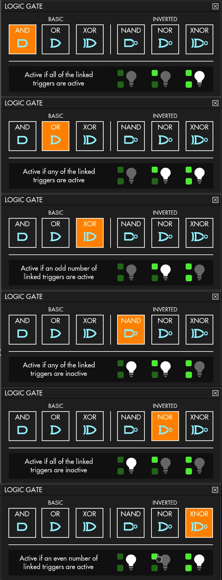
Logic Gates can be used to make creations ranging from simple two-button doors (as shown in the Handbook) to functioning computers. The Logic Gate block offers a selection of six gates: AND, OR and XOR as well as their inverses NAND, NOR and XNOR. The selected gate is displayed on the face of the block.
The connection path is critical on these blocks because they receive inputs and produce outputs. Inputs must be connected into a Logic Gate; outputs must be connected from the Logic Gate. Using two Logic Gate blocks as an example, connecting block two to block one means that the signal will be sent from block two to block one.
Advanced Use
- Logic Gates can be looped together to create latches or flip-flops. This means that Logic Gates can form memory circuits, storing a state (1 or 0).
- A Logic Gate has an output delay of 1 tick (0.025 sec).
- If you are planning a really complicated build, you might want to use the Scrap Mechanic Logic Gate Simulator.
Crafting
 |
 |

|
| 1 | 1 | 1 |

| ||
| 00:20 00:12 (Level 5) | ||

| ||
|
| ||

| ||
| 1 | ||
Save/Load Behavior
This section is only going to be of interest if you are building a circuit with a persistent state - such as a memory circuit or a repeating timer. For circuits based on the state of switches, then even if the save/load state is wrong, it'll only last for a couple ticks anyway. In memory circuits, the surprising save/load behavior can manifest as the circuit being in an unexpected state when you reload or wildly flashing on reload. In timer circuits, it usually manifests as a single-tick "true" signal in the middle of what should be a long period of "false" signals (or the other way around).
You might think that when you exit the game and come back that the logic gate would be wiped to zero on re-load and then take on its proper state after its signals get a chance to pass through it. Or you might think that the logic gate would retain the state it had when you exited the game. That would make a lot of sense, but it's not now the game actually works. Logic Gates have a saved state they will be restored to when you re-load the game or re-load a game chunk (when you return to a creation from a long way away) and that saved state is not necessarily the state that it was in when you left it. The saved state of a logic gate (and a Switch, by the way), is the state it was in the last time it was taken off a lift, had connections added or removed, or when it was painted. Confusingly, this does not hold true for Timers, whose saved state is the state they were in when they were unloaded.
The act of placing a creation on a lift clears the saved state of all switches and logic gates, causing memory circuits to enter a glitched state. Taking creations off of the lift saves the state of all the logic gates and circuits on the creation. So, for example, if you have a simple memory circuit with a couple of buttons to toggle it on and off, then when you put it on the lift, it will be flashing wildly. If you then click a button while it's on the lift, then take it off the lift, that becomes its saved state. So, for example, if you switch it to the other state, exit the game and return, you will find it back in the state it was in when you took it off the lift.